Review of electrical system upstream of the main bus
I have decided to adopt this scheme:
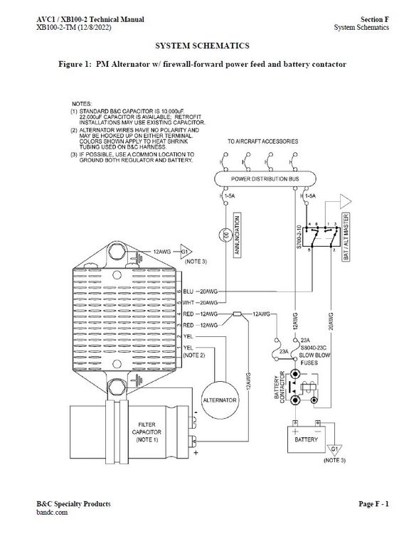
The current measuring shunt will be placed between the battery contactor and the common connection of the slow blow fuses. The introduction of the contactor permits the shunt monitoring lines to be unpowered when the master is off avoiding parasitic conduction via the EMS220 inputs (when unpowered), while also eliminating the need for main bus rails to pass both ways through the firewall. Only a single 12AWG wire passes aft through the firewall to supply the main busbar.
SO to update
Upstream of the main bus
"Master" switch is now a DPDT 3 position type without a circuit breaker
It remains to be seen whether an alternator breaker will be provided.
Details on the S700 switch
https://bandc.com/wp-content/uploads/2018/05/aec_switch_ratings.pdf
and the MS switches in general
https://www.farnell.com/datasheets/1557997.pdf
Author
This post is from Adam Dickson