Power connections for SV42 servos
The suggested schematic for the servos are
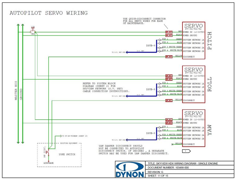
There are only pitch and roll servos in this build. The current consumption of the servos are given below
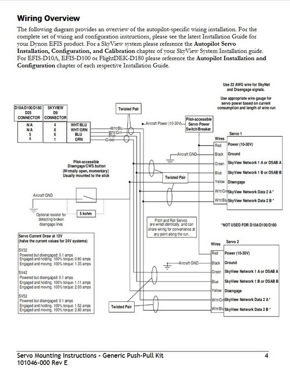
For the two SV42s working together the current draw is 4.06 amps if both servos are engaged and moving.
The pwr and gnd wires for each servo are 20AWG. These could be aggregated to a single 20AWG wire before passing though the midsection interconnect as a single size 20 pin is rated to 7.5A and the 20AWG wire easily handles this current level (Table 11-3 on page 11-15 in AC43-13-1B gives 7.5A limit)
Instead I will aggregate to a single 18AWG for passing through the midsection interconnect. Purple-band size 20 pins will be used. The breaker will be kept at 7.5A so to protect the limits of the 20AWG wires after they split off to each setvo
18AWG wire will be used on the run back to the panel
On this page
Electrical circuit breaker planning - We Build Planes
I stated
Page 11: 10A - autopilot servos (each supplied with 20AWG wire, which is limited to 5A so separate breakers required for each)
- 5A breaker for roll servo - BREAKER 10
- 5A breaker for pitch servo - BREAKER 11
The schematic was providing for 3 servos, up to SV52 - total current 3*2.8A = 8.4A, hence the 10A breaker. The 5A limit on 20AWG wire was incorrect, actually 7.5A
Given the actual setup a single 7.5A breaker is sufficient - combining both servos onto the one circuit, and using 18AWG wire after aggregation and on the panel side
Author
This post is from Adam Dickson