Revised panel CB arrangement and busbar structure
Previous post describe the revised essential and avionics bus structure, shifting of boost pump to the essentials bus, and the introduction of two additional circuit breakers
https://webuildplanes.com/adam-dickson-sling2/p/7326/need-for-two-additonal-circuit-breakers
The START and USB CBs will be moved out of the main group as follows:
- START CB below the master switch
- USB CB alongside the USB outlet
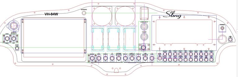
These CBs will be wired to the main bus.
As for the main grouping of 20 breakers, 19 of these divide into three sets each with their own busbar. These lists directly determine the busbar structure
Feed from the main busbar (split between top and bottom rows, on the left)
- BK CHG - IBBS charge input
- REG - regulator
- TAXI LT - taxi lights
- LDG LT - landing lights
- 4 hole 12.5mm wide busbar
- AP - autopilot servos
- NAV LT - navigation lights
- STROBE - strobe lights
- 3 hole 10mm wide busbar
Feed from the essential busbar (upper row, right hand side)
- EFIS - which then feeds the (main) EFIS toggle switch
- AVNCS - which then feeds the AVNCS toggle switch
- FLAPS - flaps
- TRIM - trim
- CAB LT - cabin light
- BOOST - boost pump
- 6 hole 12.5mm wide busbar
Feed from the avionics busbar (lower row, right hand side)
- COM - com radio
- IC - intercom
- XPNDR - transponder/ads-b in
- FLARM- flarm
- BK EFIS - backup efis
- HDST -headset
- 6 hole 12.5mm wide busbar
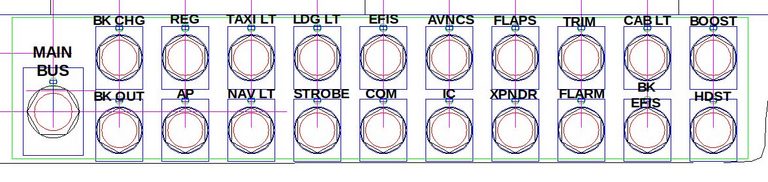
The remaining CB in this grouping of 20 - BK OUT - is separately wired, as is the MAIN BUS breaker
New busbars will need to made. A 120x120mm 1.5mm thick copper sheet is on order, which will be wide enough to span 6 CBs. The lengths and sizes are given above
The existing CBs will need to be moved around
The current arrangement is as follows:
Top row: 5, 5, 10, 10, 5, 5, 5, 5, 1, 1
Bottom row: 10, 3, 5, 5, 7.5, 10, 3, 2, 3, 1
This will be changed to:
Top row: 5, 1, 10, 10, 5, 10, 5, 2, 1, 3
Bottom row: 10, 5, 5, 5, 5, 1, 3, 3, 1, 1
There is a need to review the AVNCS CB rating, given that a number of items (like flaps) have been shifted directly onto the essentials bus. Using the data in
https://webuildplanes.com/adam-dickson-sling2/p/7174/review-of-standby-bus-breaker-ratings
the total current draw can be estimated
- COM - com radio - 2A max when transmitting
- IC - intercom - 0.1A
- XPNDR - transponder/ads-b in - 0.6A
- FLARM- flarm - 0.4A (incl flarm and trafficview)
- BK EFIS - backup efis - 0.27A
- HDST -headset - 0.1A
Total current is 3.5A - A 5A CB is more appropriate (Klixon 2TC2-5)
Author

Move boost pump to essential bus and consequences
This post is from Adam Dickson