Trim conventions and control stick wire assignments
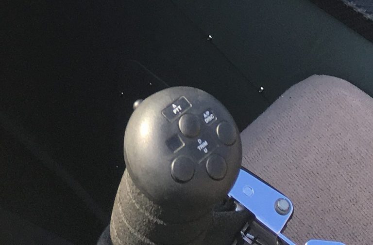
Ray Allen G405 sticks
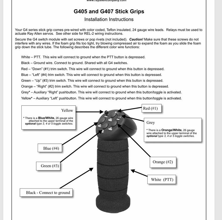
Left button - AP level - blue wire - combine before passing to the midsection connector
Right button - AP disconnect - orange wire - combine and pass directly to the AP servos disconnect wire (yellow) before passing to the midsection connector to reach the trimamp.
Top button - Trim nose down - red wire - route left and right hand sides separately through the midsection connector
Bottom button - Trim nose up - green wire - route left and right hand sides separately through the midsection connector
Front button - PTT- white wire - route left and right hand sides separately through the midsection connector
Common ground wire - black wire - combine before passing to the midsection connector
Assignments modelled on C152 trim wheel, but also consistent with an existing club Sling 2
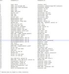
From the Ray Allen RP4 LED position indicator
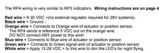
and
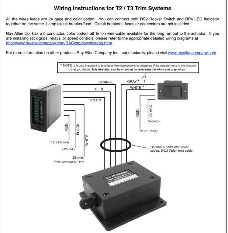
its is evident that the potentiometer inside the T2-7A has the following connectivity:
Orange and Blue wires are the end-connections, while the green wire is the wiper. This is verified the resistance between the orange and blue wires is a constant 5.035kohms, regardless of the trim motor shaft position. Given the notes above it is intended that the orange wire be connected to +5V (from the EMS220), the blue wire to ground
The resistance between the green and blue wire is 5.035kohms when the shaft is fully extended. So if the orange wire is connected to +5V the green wire will have +5V on it when the shaft is fully extended and 0V when fully retracted.
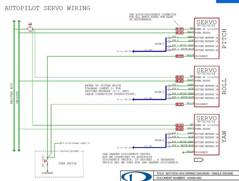
Given the Ray Allen T2-7A trim motor is mounted underneath the elevator:
Given trim nose down requires the trim tab to lift up relative to the elevator, this means the shaft of the T2-7A should extend. It is found that the grey wire driven positive relative to the white wire achieves this extension.
So given the potentiometer connectivity above, the fully extended shaft associated with trim nose fully down will result in 5V on the green wire, and the fully retracted shaft associated with trim nose fully up will result in 0V on the green wire.
When I go through the calibration procedure, setting the flap input wire (pin 23) to +5V for trim down, 0V for trim up, and 2.5V for takeoff, I find that the trim indication has the bug fully down for trim down, bug fully up for trim up. This is the opposite of the indicator convention in the Cessna 152.
I do not appear to have flexibility here - trim down/up always corresponds to the bug being down/up
I can connect the blue and orange to 0 and 5V in any way as the calibration process will absorb the transposition
Also, following the schematic conventions for trim switch connections:
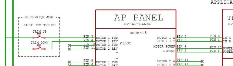
as well as
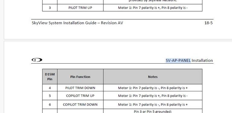
Now trim down requires shaft extension, with the grey wire driven positive relative to the white wire. So from the table above the grey wire should be connected to pin 8 and the white wire connected to pin 7. This order cannot be reversed.
Author
This post is from Adam Dickson