Connection of intercom loom to COM radio and Flarm Fusion
At this point pins 24,25 (pwr), 19,22 (gnd), 5 (data rx), 6 (data tx), and 13 (enable) are inserted into the COM RADIO D25 connector. These are all routed through the midsection interconnect to make their way to the HDX1100 and the SV-COM-PANEL
Now pins 1 (phones gnd), 2 (phones out) must be connected
Also pins 23 (mic in), 15 (ptt in), and 9 (mic/ptt gnd) must be connected
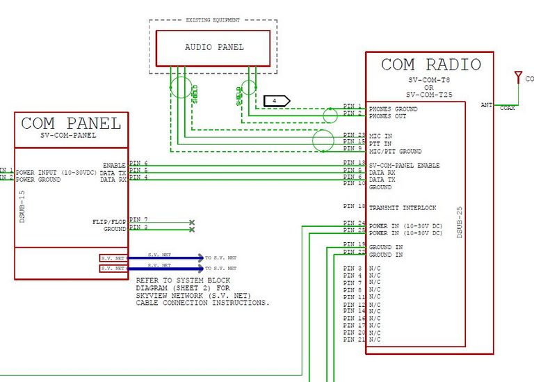
The corresponding connections (already made in the intercom loom) at the intercom are as follows
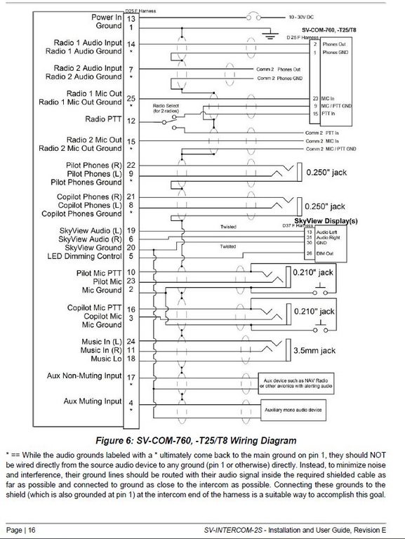
To work out WTF this means, I have peeled back the heatshrink on one or the cables on the loom coming from the intercom, and note the shield is folded back but not connected. So what the above means is that these shields should not be connected at the com-radio (or flarm end, for the muting input). Just as the schematic suggests
Either the muting or the non-muting input is connected to the flarm output. Initially I will connect the muting input.
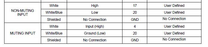
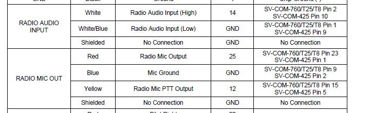
From the Flarm fusion manual, the Dsub9 connections are as follows
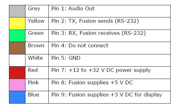
Given the * comments above, the GND wire (white/blue) of the (non-)muting input should be left unconnected, only the white wire should be connected, to pin 1 of the DB9 connector
Author
Electrical circuit breaker planning 3
This post is from Adam Dickson