Panel Design Inventory
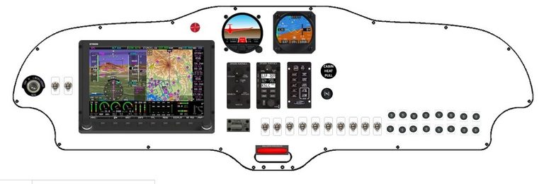
The approximate concept is
 ''
''
Note a few items are missing from this graphic, compared to the list below
Dropbox link to a directory structure which are named with the exact part numbers. Within each directory are diagrams and CAD files for the parts.
The parts are as follows, grouped by category
ELT
ACR Electronics ELT remote switch A3-06-2757
Ignition switch
ACS A-510-2 Ignition Switch
Panel USB outlet
Alfatronix PV65R-D or PVPWPp-AC panel mount USB port
Alternate static switch
Clippard TV-3S air switch - this will select between "cabin" and "outside" static
Main EFIS
Dynon SV-HDX-1100
COMS panel
Dynon SV-COM-PANEL (Vertical)
Intercom panel
Dynon SV-INTERCOM-2S (Vertical)
Autopilot panel
Dynon SV-AP-PANEL (Vertical)
Backup EFIS
Kanardia Horis 80 v2
Traffic Proximity alert
LxNav TrafficView 80
Flap switch and facade
MS35038-27 toggle switch (SPDT mom on - off -mom on)
Spruce 11-11338 Flap handle and anti-rotation
Interior lighting dimmer
Spruce 11-06674 PWM dimmer 12VDIMMEROI-7A
Warning indicator lamp
Spruce 13-15812 Pilotlights LED panel indicator lamp
Panel outline and Cubby Hole location
Sling 2 panel cubby hole mounting (reversed)
Sling 2 panel outline
Circuit breakers
Klixon 2TC2 circuit breaker (MS3350)
Toggle Switches
MS25201-4 toggle switch (progressive)
MS35038-22 toggle switch (SPST)
TE W31-X2M1G-3 toggle switch (SPST with 3A breaker)
Detailed switch arrangement and labelling.
More details in https://webuildplanes.com/adam-dickson-sling2/p/7032/electrical-circuit-breaker-planning-3
The switches are chosen such they are all off in the "down" position, for easy inspection. Some of the switches are three position, with the "middle" and "up" paddle position corresponding to two different "on" states. To achieve this, the "progressive" type of switch is used (MS25201-4). All other switches are SPST (MS35038-22) with the exception of the fuel pump switch (TE W31-X2M1G-3) which has an integral breaker. The reason for combining the switch and the breaker is to enable rapid resetting in an emergency while minimising traverses of the panel under such circumstances
Engine switches
Two switches are located to the left of the Main EFIS, alongside the ignition switch. These are from left to right
"MASTER" - progressive: down = OFF, middle = BAT, up = ALT
"FUEL PUMP" - SPST with breaker: down = OFF, up = ON
Flap switch
The flap switch a bit of an exception, so it is located away from the other switches and made prominent by use of a paddle and an anti-rotation bezel. The switch type is SPDT with a paddle centre-off position and momentary paddle up/down positions for flaps up/down respectively. This switch has its own machined bezel (contained in the link above) so does not require additional marking.
Main switch Bank
The remainder of the switches are places in the middle and should be arranged in a single line as a priority. The circuit breaker arrangement (here presumed to be two rows of eight) is a secondary priority.
This aircraft has a 6AH "IBBS" backup battery which can power many of the aircraft systems in the event of a main bus fail. The main EFIS can be switched between the main bus and the IBBS output with the following dedicated "Main EFIS" switch.
The backup system can be disconnected from the main bus with the following switch (a little redundant since there is a CB which can be pulled)
"BACKUP INPUT" - SPST: down = OFF, up = ON
The main EFIS can be selectively powered from the main or backup bus.
"MAIN EFIS" - progressive: down = OFF, middle = BACKUP, up = MAIN
Several other systems (Comms, Transponder, Flarm/TrafficView, Flaps, and Trim) can also be manually switched as a group between the main bus and the IBBS output with the following dedicated "Avionics" switch
"AVIONICS" - progressive: down = OFF, middle = BACKUP, up = MAIN
The idea behind this is that all the basic instrumentation, communications and controls (except autopilot) are available in the event of a main bus failure. The engine is a 912ULS so it will keep running also. Note that both the main and backup EFIS also have their own individual backup battery which will last a short while. These individual backup batteries are to be regarded as a last resort, where even the main backup battery system fails. The idea of the main backup battery is to permit sustained aircraft operation in the event of a main bus failure with pretty much full operation.
The following items are switched only off the the main bus. These services are lost in the event of a main bus failure
"LAND" - progressive: down = OFF, middle = WIGWAG, up = ON
"TAXI" - SPST: down = OFF, up = ON
"STROBE" - progressive: down = OFF, middle = BEACON, up = +WINGS
"NAV" - SPST: down = OFF, up = ON
"CABIN LIGHT" - progressive: down = OFF, middle = RED, up = WHITE
"AUTO PILOT" - SPST: down = OFF, up = ON
"USB" - SPST: down = OFF, up = ON
Since all switches are in the off state when down, the "OFF" graphic can possibly be omitted to reduce clutter, as in the photo above
Detailed circuit breaker arrangement and labelling.
More details in https://webuildplanes.com/adam-dickson-sling2/p/7032/electrical-circuit-breaker-planning-3
The circuit breakers are in two rows of 8 units. Hopefully these will fit into the presumed arrangement
Upper row, from left to right
"MAIN EFIS" breaker - Klixon 2TC2-5
"COMMS" - Klixon 2TC2-5
"TRANSPONDER" - Klixon 2TC2-5
"FLARM/BACKUP EFIS" - Klixon 2TC2-5
"FLAPS" breaker - 2TC2-7.5
"TRIM" breaker - 2TC2-5
"AUTO PILOT" - 2TC2-7.5
"HEADSET" - 2TC2-2
Lower row, from left to right
"BACKUP IN" - Klixon 2TC2-10
"BACKUP OUT" - Klixon 2TC2-10
"BACKUP CHARGE" - Klixon 2TC2-7.5
"USB" - Klixon 2TC2-10
"LAND" - Klixon 2TC2-10
"TAXI" - Klixon 2TC2-10
"NAV/STROBE" - Klixon 2TC2-10
"CABIN" - Klixon 2TC2-5
Author
This post is from Adam Dickson