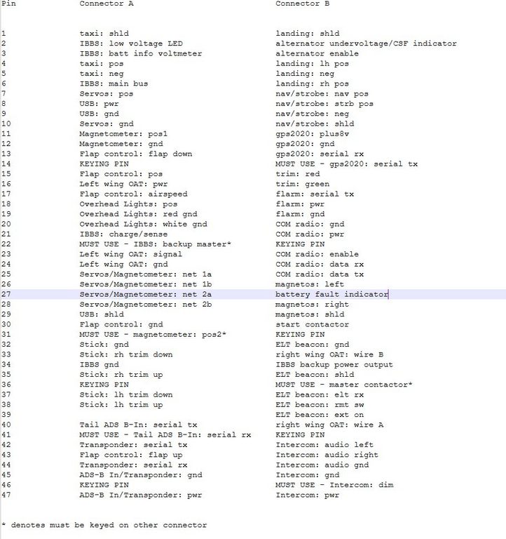
HDP20 pin assignments - part 1
Connect A (front)
Taxi lights
- 3 size 16 pins, pos (4), neg (5), shld (1)
IBBS battery (shared with B connector)
- 1 size 16 pin (13A rating) - main aircraft bus (3 20AWG wires from DB15 wires condensed into 1 pin) (6)
- 1 size 16 pin (13A rating) - gnd (3 20AWG wires from DB15 wires condensed into 1 pin) (34)
- 4 size 20 pins, charge/sense, low voltage warning LED, batt info volt meter, backup power master
Tail ADS B-In
- 2 size 20 pins, serial rx, serial tx
Transponder
- 2 size 20 pins, serial rx, serial tx
Tail ADS B-in/Transponder
- 2 size 20 pins, pwr, gnd
Stick
- 5 size 20 pins, lh trim up, lh trim down, rh tirm up, rh trim down, stick gnd (omit AP disconnect)
Servos
- 2 size 20 pins, pos, neg
Magnetometer
- 3 size 20 pins, pos1, pos2, gnd
Servos/Magnetometer
- 4 size 20 pins, net 1a, net 1b, net 2a, net 2b,
USB
- 3 size 20 pins, pos, neg, shld
Overhead lights
- 3 size 20 pins, white gnd, red gnd, pos
Flap control
- 5 size 20 pins, pos, gnd, flap up, flap down, airspeed
Left wing OAT
- 3 size 20 pins, signal, pwr, gnd
A subtotal
38 size 20, 5 size 16
3 keying pins
Connect B (aft)
IBBS battery
- 1 size 16 pin (13A rating) - backup power output (4 20AWG wires from DB15 condensed into 1 pin) (34)
- on the other connector this is connected to GND so the consequence of swapping connectors will be a blown fuse on the output of the IBBS but this can be avoided if the backup power master on the other connected is assigned to a pin that corresponds to something that is not grounded on this connector
Landing lights
- 4 size 16 pins, lh pos (4), rh pos (6), neg (5) , shld (1)
Nav/strobe lights
- 4 size 20 pins, nav pos, strb pos, neg, shld
GPS2020
- 4 size 20 pins, plus8v, gnd, serial rx, serial tx
Trim
- 2 size 20 pins, red, green
Flarm fusion
- 3 size 20 pins, serial tx, pwr, gnd
COM radio
- 5 size 20 pins, gnd, pwr, enable, data rx, data tx
Magnetos
- 3 size 20 pins, left, right, common shield
Start contactor
- 1 size 20 pin pull up
Master contactor
- 1 size 20 pin pull down (not counted due to Strategy 2)
Alternator enable
- 1 size 20 pin
Alternator undervoltage/CSF indicator
- 1 size 20 pin
Battery fault indicator
- 1 size 20 pin
Intercom
- 6 size 20 pins, audio left, audio right, audio gnd, dim, pwr, gnd
Right wing OAT
- 2 size 20 pins
ELT beacon
- 5 size 20 pins, gnd, shld, elt rx, rmt sw, ext on
Reserve 1 pin on connector B as blank as counterpart of backup power master pin on connector A
Reserve 1 pin on connector B as blank as counterpart to the pos 2 pin on connector A
For both of these, use of a pin that is keyed on connector B means there is no penalty
B subtotal
39 size 20, 5 size 16
3 size 20 keying pins
What about trying to make the electrics resilient against swapping the connectors, assuming the keying pins are absent - an exercise?
Scheme 1
Suppose, in the future it is necessary to remove the keying pins because of a need for additional connectivity. Then there is nothing to prevent an accidental swap of the connectors A and B. Strategies exist to prevent accidental damage.
Strategy 1
The master contactor pin number on connector B is left unused on connector A. If the socket A is accidently placed onto connector B then the master contactor is not energised and so the main bus is not energised.
Strategy 2
The backup master pin on connector A is left unused on connector B. If the socket B is accidently placed onto connector A then the backup master is not energised and so the backup bus is not energised
Strategy 1 and 2 can take advantage of the the presence of the keying pin - when still present - by making use of of the "must use" positions that match the keying pin. If and when the keying pin is removed, the contact must not be used. Ergo, there will be no point in removing the keying pin
Strategy 3
Assign any lines on one connector that can source significant current, that if the connectors are swapped, are passed into lines that can absorb significant current. The candidates for these are pwr pins and pins carrying signals with significant drive capability
Strategy 4
The start contactor pin should have its counterpart pin on the other connector as ground
As part of Strategy 3, here is the allocation of the candidate pins. The signals should be aligned on corresponding pins. I have attempted to match the AWG of the associated wires as much as possible. If swapped the power or drive source coming from one receptacle can more-or-less drive into the power inputs on the other plug, without causing damage. As stated above, this cannot ever happen owing to the use of keying pins and the master contactor lockout
Connector A Connector B
size 16:
taxi: pos landing: lh pos
IBBS: main bus landing: rh pos
size 20:
Servos: pwr Nav/Strb lights: nav pos
USB: pwr Nav/Strb lights: strb pos
ADS-B In/Transponder: pwr Intercom: pwr
Magnetometer: pos1 GPS2020: plus8v
Magnetometer: pos2 left blank
Overhead Lights: pos Flarm Fusion: pwr
Flap control: pos Trim: red
Left wing OAT: pwr Trim: green
IBBS:
Also, as per the comments above. This backup power output is unique is that it is a potentially driven pin. So a swapped socket is arranged to short it to ground, if somehow the backup master happened to be grounded. The 10A fuse in the IBBS will blow as a protection without damaging any wires.
IBBS: gnd IBBS: backup pwr output
Something: gnd Starter contactor
Proposed pin assignment (which presumed 4 keying pins in each connector, as I had overlooked 3 signals)

Scheme 2
I overlooked three signals above (the top list has been revised) so I had to reduce the number of keying pins from 4 to 3. If I assume keying pins will be present the possibility of swapping connectors does not exist. I can achieve this event with 1 keying pin on each connector. So long as I have keying pins, the strategies above are not needed.
But suppose I try to work the strategies - let's see if it is workable. I add some additional measures
IBBS: batt info voltmeter on connector A is associated with alternator enable on connector B, so if swapped the live alternator enable is passes into an EMS220 voltage measuring input which can take it
The overhead lights red and white gnds on connector A are associated with flarm and com radio gnds so both lights power up if the connectors are swapped, and if somehow the main bus is energised
The left magneto on B is associated with left wing OAT gnd on A, while the right magneto on B is associated with ???
I have tried to match grounds but I cannot get at them all. The possibilities of various parasitic conduction paths through signal lines is large, not to mention the impact of shorted or conflicted signal lines which has not even been considered
It is all getting too fucking hard - and I have not even tried to optimise the physical arrangement of the wires on the connectors - the numbers are scattered all over the back of the connector.
I am not going to bother - I will assume the use of keying pins to absolutely prevent exchange of the connectors!!
Author

This post is from Adam Dickson
HDP20 pin assignments - part 2