HDP20 pin assignments - part 2
So I am going to insert the pins, after swapping the engine control (start, magneto, etc) flaps and trim, to the front connector to get them far away from the audio stuff and because the engine control lines are a little short. I am also not inserting the magnetometer lines, deciding to route the magnetometer cable (with its own plug) all the way to the panel. 4 pins are freed up, and I do not have to address the question of whether or not the +12 auxillary power is actually required by the magnetometer. I did not include it. Online discussion says it is not included, but I have learned to distrust such forum talk, or worse, AI. Little is gained by including the magnetometer into the midsection interconnect, and by keeping it separate will facilitate debugging of any subsequent network issues, by enabling the servos to be fully separated from the rest of the network including the magnetometer. I also don't have to redo a bunch of cable splices. In addition, the backup EFIS, likely a Kanardia Horis, will have its own CAN bus-based remote magnetometer. This will be also connected by a cable which will pass directly from the panel though the midsection, also bypassing the interconnect. For this particular cable, there are two reasons for bypassing the interconnect. The first is that the CAN bus has a controlled impedance transmission line, which could be disrupted by being passed through the interconnect. Second, there are just not enough spare wires. Some pins could be liberated by consolidating a shield or two, or a ground, but the payoff does not seem so great merely in the pursuit of "purity" (i.e. everything passing thought the interconnect). Hell, the pitot static lines don't, so I am not going to get bent out of shape about two rather than one electrical cables not passing though the interconnect.
I also added 2 lines for the fuel pump, which I had forgotten about
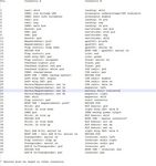
So the revised scheme is this:
Connect A (front)
Taxi lights
- 3 size 16 pins, pos (4), neg (5), shld (1)
IBBS battery (shared with B connector)
- 1 size 16 pin (13A rating) - main aircraft bus (3 20AWG wires from DB15 wires condensed into 1 pin) (6)
- 1 size 16 pin (13A rating) - gnd (3 20AWG wires from DB15 wires condensed into 1 pin) (34)
- 4 size 20 pins, charge/sense, low voltage warning LED, batt info volt meter, backup power master
Tail ADS B-In
- 2 size 20 pins, serial rx, serial tx
Transponder
- 2 size 20 pins, serial rx, serial tx
Tail ADS B-in/Transponder
- 2 size 20 pins, pwr, gnd
Stick
- 5 size 20 pins, lh trim up, lh trim down, rh tirm up, rh trim down, stick gnd (omit AP disconnect)
Servos
- 6 size 20 pins, pos, neg net 1a, net 1b, net 2a, net 2b,
Magnetos
- 3 size 20 pins, left, right, common shield
Start contactor
- 1 size 20 pin pull up
Master contactor
- 1 size 20 pin
Alternator enable
- 1 size 20 pin
Alternator undervoltage/CSF indicator
- 1 size 20 pin
Battery fault indicator
- 1 size 20 pin
Trim
- 2 size 20 pins, red, green
Flap control
- 5 size 20 pins, pos, gnd, flap up, flap down, airspeed
Fuel pump
- 2 size 20 pins, red, black
A subtotal
Signal/pwr pins: 38 size 20, 5 size 16
So all size 16 pins used, and 1 size 20 pin spare
Connect B (aft)
IBBS battery
- 1 size 16 pin (13A rating) - backup power output (4 20AWG wires from DB15 condensed into 1 pin) (34)
Landing lights
- 4 size 16 pins, lh pos (4), rh pos (6), neg (5) , shld (1)
Nav/strobe lights
- 4 size 20 pins, nav pos, strb pos, neg, shld
USB
- 3 size 20 pins, pos, neg, shld
Overhead lights
- 3 size 20 pins, white gnd, red gnd, pos
GPS2020
- 4 size 20 pins, plus8v, gnd, serial rx, serial tx
Flarm fusion
- 3 size 20 pins, serial tx, pwr, gnd
COM radio
- 5 size 20 pins, gnd, pwr, enable, data rx, data tx
Intercom
- 6 size 20 pins, audio left, audio right, audio gnd, dim, pwr, gnd
Left wing OAT
- 3 size 20 pins, signal, pwr, gnd
Right wing OAT
- 2 size 20 pins
ELT beacon
- 5 size 20 pins, gnd, shld, elt rx, rmt sw, ext on
B subtotal
Keying pins: 3 size 20
Signal/pwr pins: 38 size 20, 5 size 16
So all size 16 pins used, and 1 size 20 pin spare
Author
This post is from Adam Dickson