Total rethink of battery and regulator thermocouple wiring and design
The defects in the original EGT wiring are addressed in
https://webuildplanes.com/adam-dickson-sling2/p/7363/rework-of-egt-thermocouple-wiring
where I plan to introduce K-type mini-connectors firewall forward which transitions the EGT probe cables to teflon-insulated type-K wire which run all the way to the EGT input of the EMS220 DB25 connector
However, two recent posts
https://webuildplanes.com/adam-dickson-sling2/p/7352/placement-and-wiring-of-battery-thermocouple
and
https://webuildplanes.com/adam-dickson-sling2/p/7350/placement-and-wiring-of-regulator-thermocouple
need to be completely re-engineered
They have similar issues to the EGT wiring, but there is more. In common with the first link, I need to replace the copper wire running from the K-type connector all the way to the EMS220. Fortunately I had only implemented the regulator system.
The additional issues is that if I use the DB25 lines, I cannot use the CHT input rather I must use the EGT inputs. The reason is that these inputs have pre-amplifiers of fixed but differing gains suited to respectively type K and J thermocouples. In the configuration library these hardware gains are factored out of the coefficients contained therein before determining the multiplicative constant applied to the relevant ADC output. There is a false appearance that these inputs are interchangeable. Forcing the use of the CHT input, with a type K thermocouple attached, will result in error. Even if the two remaining EGT (Type K) inputs are utilised instead of the CHT input proposed in the link the system will not work as EGT temps below 370 celsius are blanked out.
The only solution is to use the general purpose thermocouple inputs on the DB37 connector, pins 27,28 and 36,37
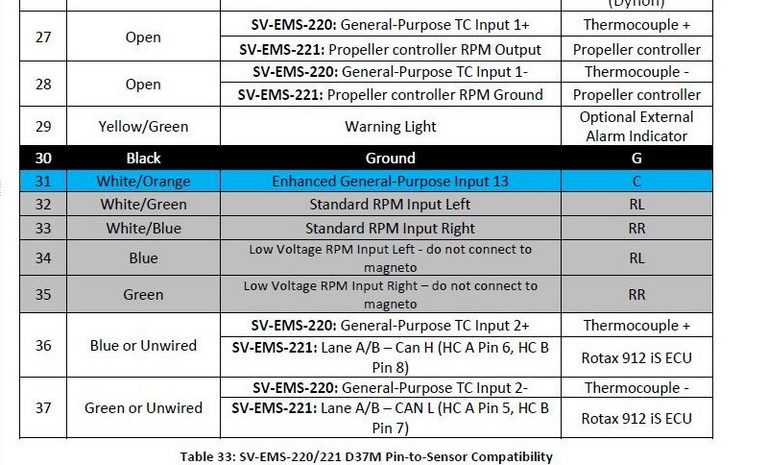
These inputs have a more advanced design allowing use with either type J or K thermistors. A higher resolution ADC combined with a programmable gain preamplifier allows optimal performance at low temperatures, even with a type K thermistor.
I have already purchased Type K mini-connectors, extension cable, and patch thermistors, so these ports will be so configured. The temperature accuracy will be about 4 Celsius for readings up to 80 Celsius (the operating limits of the regulator and survival limit of the EXT900 battery). This accuracy is quite sufficient for warning purposes.
Fortunately, from
https://webuildplanes.com/adam-dickson-sling2/p/6916/ems220-pin-assignments
the above mentioned TC input pins are currently not utilised, so the assignments will be as follows:
C37 P27 regulator thermocouple + (yellow wire)
C37 P28 regulator thermocouple - (red wire)
C37 P36 battery thermocouple + (yellow wire)
C37 P37 battery thermocouple - (red wire)
When stripping back the EMS220 DB25 of the regulator TC and EGT copper wires, the original EGT positions will be retained
Pins 19, 21, 23, 25 are positive so go to the white thermistor leads and multicoloured tefzel wires in the loom
Pins 7, 9, 11, 13 are negative so go to the black thermistor leads and associated black tefzel wires in the loom
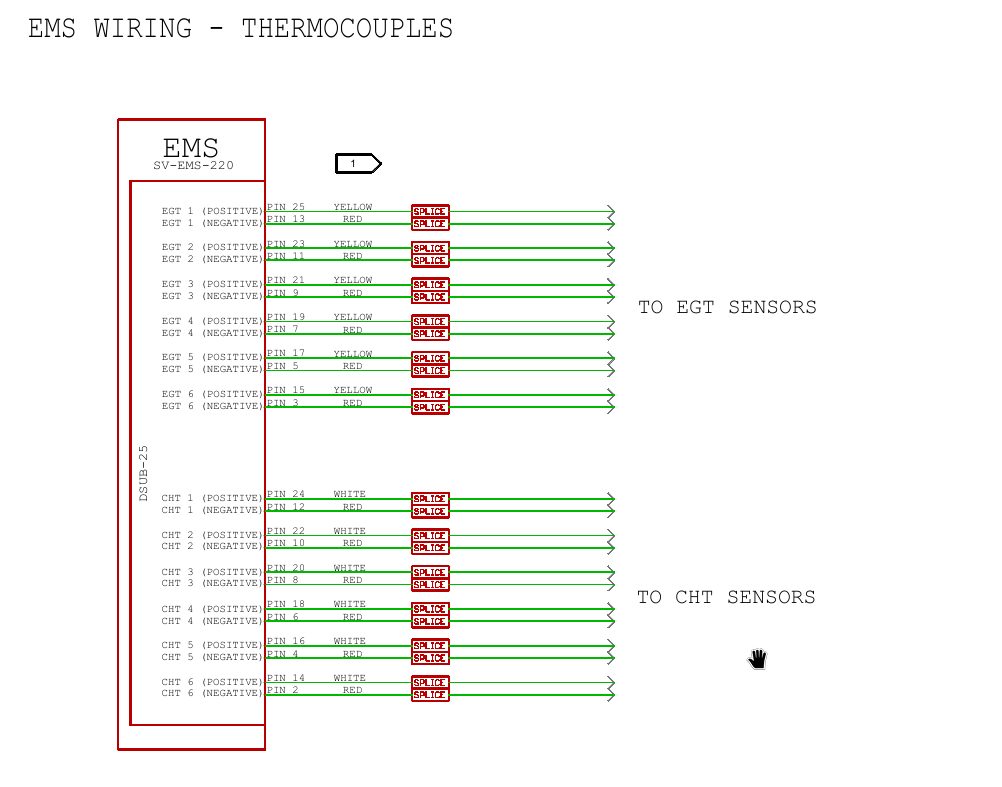
C25 P19 EGT 4 + yellow cable wire
C25 P7 EGT 4 - red cable wire
C25 P21 EGT 3 + yellow cable wire
C25 P9 EGT 3 - red cable wire
C25 P23 EGT 2 + yellow cable wire
C25 P11 EGT 2 - red cable wire
C25 P25 EGT1 + yellow cable wire
C25 P13 EGT1 - red cable wire
At each mini-connector firewall forward connector
white EGT wire (+ve) connects to yellow cable wire
black EGT wire (-ve) connects to red cable wire
Author


This post is from Adam Dickson