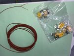
Trim motor wiring check
A previous post
has the section
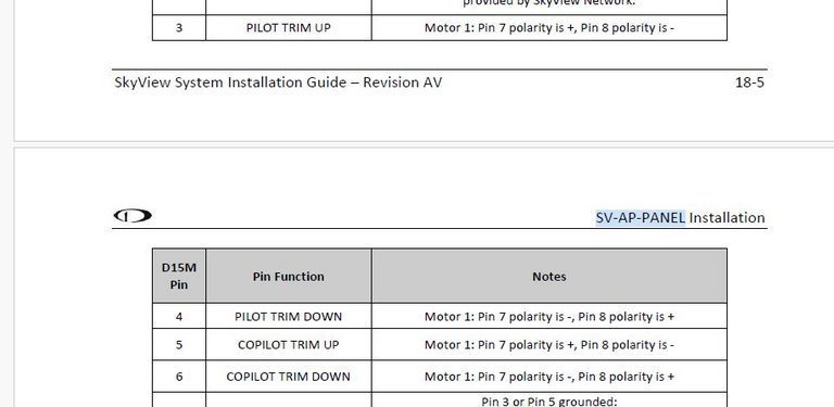
Now trim down requires shaft extension, with the grey wire driven positive relative to the white wire. So from the table above the grey wire should be connected to pin 8 and the white wire connected to pin 7. This order cannot be reversed.
In the post
https://webuildplanes.com/adam-dickson-sling2/p/6939/hdp20-pin-assignments-finalisation
the section
Trim
- 2 size 20 pins
- red (44)
- grn (43)
leaves the actual connections undefined. This red/green convention runs right to the back of the fuselage, where a 6 pin connector has the following wires labelled
- white wire currently labelled GRY
- white/red stripe currently labelled RED
- white/green stripe currently labelled GRN
- white/blue stripe currently labelled BLU
- white/orange stripe currently labelled ORG
These labels are were originally to be associated with the T2-7A wire colours, but this was forgotten along the way and the labels now have no such association, and will not be mentioned further. At some point the labels will be removed.
First task, to decipher the function of the T2-7A wires:
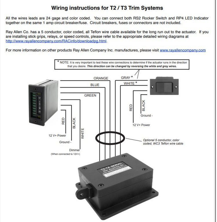
https://www.rayallencompany.com/RACmedia/instructionsT2andT3.pdf
The above page is very unclear, but the following notes on the Ray Allen position indicator helps clarify
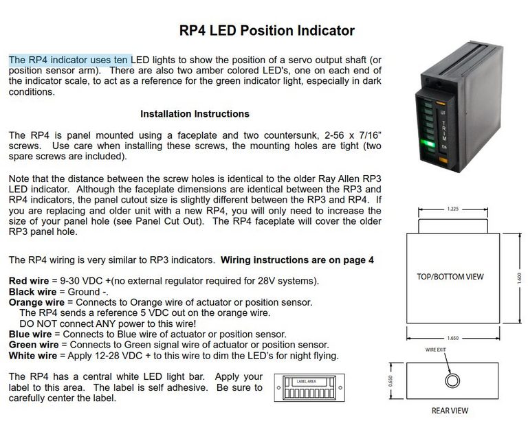
So clearly
the orange wire of T2-7A is intended as the +5V end of the potentiometer, and the blue and green wires are in no specified order the wiper and the ground end of the potentiometer
But from the Sling wiring diagrams
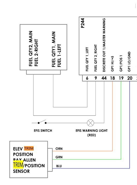
Clearly green wire is the wiper and the blue wire is the low side
From another Sling wiring diagram, the same association is made

This is consistent with
https://webuildplanes.com/adam-dickson-sling2/p/6862/trim-conventions-and-control-stick-wire-assignments
Second task, to verify the actual functions of the wires on the rear fuselage connector
Now need to verify that the the potentiometer wires are correctly routed to the EMS220 system
Also need to verify which wires are actually running to pins 43 and 44 of the HDP20 connector
I have not properly recorded these assignments so will have to buzz out the connections
With help of
https://webuildplanes.com/adam-dickson-sling2/p/6916/ems220-pin-assignments
Using images and tables contained therein
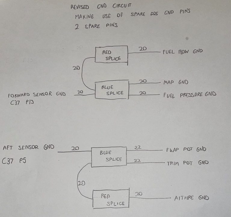
and
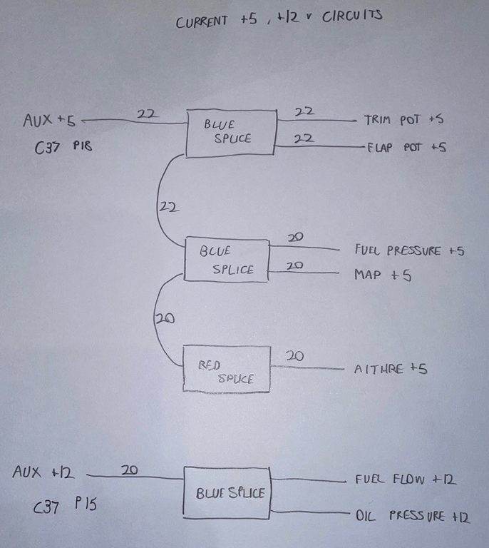
Check connectivity to 6 pin Deutsches connector at back of fuselage
- (pot low - ground circuit) Check C37 P5 connectivity - white/blue stripe verified
- (pot high - +5 aux circuit) Check C37 P18 connectivity - white/orange stripe verified
- (pot wiper) Check C37 P23 connectivity - white wire verified
Also check trim motor connectivity
HDP20 connector A
- Checked HDP20 A pin 44 "red" connects to the white/red striped wire at the rear connector
- Checked HDP20 A pin 43 "green" connects to the white/green striped wire at the rear connector
As noted the intended association with the T2-7A wire colours has not been followed.
This loss of association arises from the time the midsection interconnect was put together. The 5-core cable running from the rear fuselage transitions to a 3 core cable running to the EMS220 and wires split off to terminate at the HDP20.
The arbitrary assignment will now be made
- HDP20 A pin 44 "red" will be associated with motor output A (pin 7 on DB15)
- HDP20 A pin 43 "green" will be associated with motor output B (pin 8 on DB15)
But given the above:
Now trim down requires shaft extension, with the grey wire driven positive relative to the white wire. So from the table above the grey wire should be connected to pin 8 and the white wire connected to pin 7. This order cannot be reversed.
Therefore
- the white/green of the rear connector should be connected to the gray T2-7A wire
- the white/red of the rear connector should be connected to the white T2-7A wire
Some further images were taken of the junction between the 5-way cable running to the rear fuselage, the 3-way running to the EMS220 connector, and the individual drive wires going to the midesction interconnect, shown below
As expected the red/green trim actuation wires going to the midsection interconnect do indeed connect to the respectively white-red/white-green wires running to the rear fuselage.
The white-orange wire of the 3-way cable running to the EMS220 does connect to the white-orange wire of the 5-way cable running to the rear fuselage
Same is true for the white-blue and white wires respectively
Now (photo evidence needed) at the EMS220 connector, given the way I was building the EMS220 loom
- the white-blue wire would have been connected to aft-sensor gnd (C37 P5)
- the white-orange wire would have been connected to +5 AUX (C37 P18)
- the white wire would have been connected to the trim pot wiper (C37 P23)
This is consistent with the above measurements.
So in summary, at the rear connector, the following assignments must be made
- white-blue (aft sensor gnd) of the rear connector should be connected to the blue T2-7A wire
- white-orange (+5 aux) of the rear connector should be connected to the orange T2-7A wire
- white (pot wiper) of the rear connector should be connected to the green T2-7A wire
- The white-green of the rear connector should be connected to the gray T2-7A wire
- The white-red of the rear connector should be connected to the white T2-7A wire
The trim motor was wired as per the above, and tested, as in the photos below. Summary
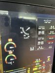
Fully trim down - top stick button - actuator extended - panel display needle at bottom of range
Fully trim up - bottom stick button - actuator retracted - panel display needle at top of range
This is all consistent with
Orange and Blue wires are the end-connections, while the green wire is the wiper. This is verified the resistance between the orange and blue wires is a constant 5.035kohms, regardless of the trim motor shaft position. Given the notes above it is intended that the orange wire be connected to +5V (from the EMS220), the blue wire to ground
The resistance between the green and blue wire is 5.035kohms when the shaft is fully extended. So if the orange wire is connected to +5V the green wire will have +5V on it when the shaft is fully extended and 0V when fully retracted.
Given the Ray Allen T2-7A trim motor is mounted underneath the elevator:
Given trim nose down requires the trim tab to lift up relative to the elevator, this means the shaft of the T2-7A should extend. It is found that the grey wire driven positive relative to the white wire achieves this extension.
So given the potentiometer connectivity above, the fully extended shaft associated with trim nose fully down will result in 5V on the green wire, and the fully retracted shaft associated with trim nose fully up will result in 0V on the green wire.
When I go through the calibration procedure, setting the flap input wire (pin 23) to +5V for trim down, 0V for trim up, and 2.5V for takeoff, I find that the trim indication has the bug fully down for trim down, bug fully up for trim up. This is the opposite of the indicator convention in the Cessna 152.
from
As remarked above, there is no flexibility about the bug on the screen. The screen indicates state, with the bug at the top of the indicator meaning "trimmed up" etc, while the stick button positions are more action- oriented. If, for example, if one is pulling back on the stick to maintain attitude, then one pushes on the aft button (trim up) until the stick forces drop to zero.
Author

This post is from Adam Dickson